Fatigue Design Diagram
Fatigue Design Diagram (FDD) incorporates compressive residual stress in metallic components & is a recognized method of enhancing fatigue strength. However, credit is seldomly taken for residual stress in design because it may not be stable, reproducible, or a reliable method of including it in the design.
The Fatigue Design Diagram provides a means of designing compressive residual stress distributions into metallic components for optimal fatigue performance and mitigation of typical damage conditions such as foreign object damage and corrosion. The patented FDD tool determines the appropriate level and the depth of compressive residual stresses from surface treatments such as LPB® and shot peening.
How does it work?
During the design process of a metallic component, applied stresses are generally determined by using finite element analysis to ensure a part can withstand the applied loads either in yielding or fatigue. To reduce the applied stresses, designers can modify the geometry by adding material in critical regions or by using a material with more desirable properties. Utilizing the FDD method, the designer can reliably use compressive residual stresses to offset the applied stresses, thereby improving performance.
FDD features
- Predicts fatigue behavior in the presence of both damage and residual stress
- Provides a design guideline for determining the compressive residual stress magnitude needed to achieve a target damage tolerance
- Allows reduced use of excess material in part design providing significant weight savings and lower production costs
- Enhanced part life and performance reduces maintenance and replacement costs as well as costly downtime

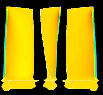
FEA of a blade with FDD compression incorporated

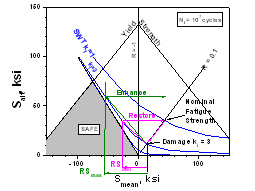
Demonstration of FDD to determin the minimum RS requirement to mitigate damage and the maximum RS to enhance performance

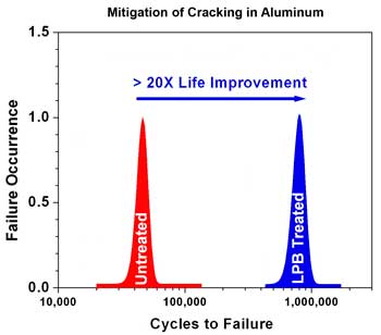
Fatigue Life Improvement in Aluminum with FDD configured compression
Questions about fatigue design diagram needs?

